Title: Number-Resolved Photocounter for Propagating Microwave Mode
Authors: Rémy Dassonneville, Réouven Assouly, Théau Peronnin, Pierre Rouchon, Benjamin Huard
Institution: Univ Lyon, ENS de Lyon, Univ Claude Bernard, CNRS, Laboratoire de Physique, F-69342 Lyon, France
Manuscript: Published in Physical Review Applied [1], Open Access on arXiv
Introduction
Quantum technologies, based on superconducting circuits and microwave photons, are rapidly developing. At the heart of these devices are superconducting qubits, highly customizable and capable of strong interactions with microwave photons [2]. This basic building block enables everything from multi-qubit quantum processors to state of the art sensors. One capability missing from the toolkit of superconducting qubits is the ability to detect propagating photons, which can be used to send quantum information over long distances. Developing a method to resolve the number of photons contained in a wavepacket traveling down a transmission line could unlock the ability to construct quantum networks, entangle remote qubits, and build quantum sensors.
The strong interactions between qubits and photons make qubits an ideal device for photon detection. In a stationary mode, the photons can be held for a long time, allowing a qubit to distinguish between 0, 1, 2, … photons [3]. However, a propagating wavepacket travels so quickly that the qubit only has enough time to determine if there are an even or odd number of photons. In this work, the authors devise a scheme to catch an arbitrary signal propagating down a microwave transmission line and efficiently count the number of photons in the wavepacket [1]. I first describe the device and its components used to make this possible. Next, I go through the catch protocol, useful for holding a wavepacket for long enough to be measured. I break down the photon counting measurement that resolves 

Device


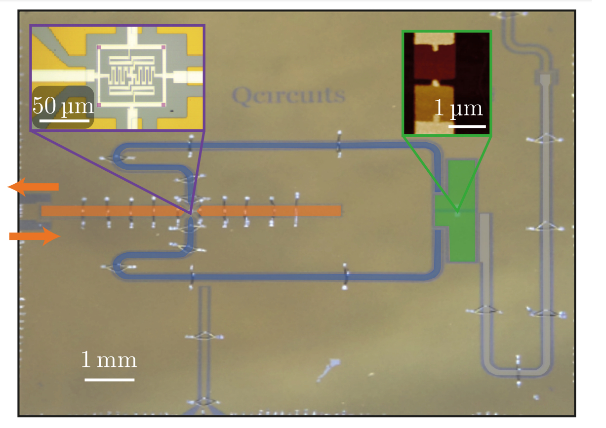
The device consists a series of carefully designed microwave components as shown in Figure 1. A propagating wavepacket first encounters a buffer cavity, a superconducting 

Catching Photons
A Josephson ring modulator (JRM) is a device used to swap the states of two cavity modes. In this work, it is used to transfer the wavepacket captured in the leaky buffer cavity into the long lived memory cavity. The JRM is pumped at the frequency corresponding to the difference between the buffer (resonant frequency 


Counting Photons
Once the wavepacket is successfully transferred into the long lived memory cavity, the qubit and readout are used to count the number of photons present. The authors make a series of measurements to resolve the photon number of the wavepacket. Each measurement involves allowing the qubit and memory cavity states to interact for a carefully chosen amount of time. At the end of each measurement the qubit state (ground, g or excited, e) is read out and recorded. The authors devise protocol that requires making the minimal number of measurements: resolving up to 


| Bit 0 | Bit 1 | Number |
| 0 | 0 | 0 = 0(20) + 0(21) |
| 1 | 0 | 1 = 1(20) + 0(21) |
| 0 | 1 | 2 = 0(20) + 1(21) |
| 1 | 1 | 3 = 1(20) + 1(21) |
Binary decomposition measurement protocol
The measurement harnesses the interaction between the qubit and memory cavity a described by the Hamiltonian in Equation 2. The memory creation and annihilation operators are represented as 


Without the interaction between the qubit and memory cavity, the Hamiltonian of the just the qubit would look like 


To access the memory cavity photon number requires multiple similar, but subtly slightly different measurements, all relying on the interaction that causes a qubit frequency shift proportional to the number of memory photons. In each measurement, the authors entangle the cavity state with that of the qubit. This is done by placing the qubit in a superposition state 


In the first measurement, the goal is to distinguish between even and odd photon numbers, 0/2 or 1/3, the 0th bit of information. The interaction time is chosen to be 


In the second measurement, the interaction time is halved to be 

The series of qubit states depending on the memory photon number is shown in Table 2. This protocol realizes the binary decomposition shown in Table 1 where the qubit ground state (g) serves as a 0 and the excited state (e) as 1.
| 1st Result | 2nd Result | Photon Number |
| g (0) | g (0) | 0 |
| e (1) | g (0) | 1 |
| g (0) | e (1) | 2 |
| e (1) | e (1) | 3 |
Counting more photons
In order to measure wavepackets with even larger photon number, the series of measurements can be extended to extract more bits of information. For each bit, a measurement similar to the ones described above would be performed, where the axis of rotation for the second
Large integer values can be represented by only a few bits, for example integers up to 


Future outlook
The authors devise a protocol to catch an arbitrary wavepacket by capturing it in a buffer cavity and swapping it into a long lived memory cavity. Once the wavepacket is in the memory cavity, a qubit is used to count the number of photons contained using the minimal number of measurements. In this work, the authors are able to distinguish between 0, 1, 2, 3 photons in a wavepackets.
This device can serve as a central component of a quantum network. Quantum information can be encoded into a wavepacket with different superpositions of photon numbers. The information can be transported along a transmission line to a secondary location, where the device presented in this work can capture and readout out the information stored by assessing the photon number of the wavepacket. The photon detection and counting component can also be used to entangle remote qubits. An emitter qubit can be coupled to a transmission line such that the qubit state is encoded as a wavepacket with a superposition of different photon numbers. This wavepacket can be transported along a transmission line to a remote receiver qubit. By counting the wavepacket photon number, the state of the receiver qubit can be conditioned on the number of photons in the wavepacket, and by extension the state of the original emitter qubit. Finally, by combining the two techniques described in this work, the device can be used as a quantum sensor, with potential applications in dark matter searches and gravitational wave detection. An arbitrary microwave signal can be caught efficiently and distinguished from backgrounds by measuring the number of photons in the wavepacket.
References
[1] Dassonneville, R., Assouly, R., Peronnin, T., Rouchon, P. & Huard, B. Number-resolved photocounter for propagating microwave mode. Physical Review Applied 14 044022 (2020).
[2] Wallraff, A. et al. Strong coupling of a single photon to a superconducting qubit using circuit quantum electrodynamics. Nature 431, 162–167 (2004).
[3] Schuster, D. I. et al. Resolving photon number states in a superconducting circuit. Nature 445, 515–518 (2007).
Akash Dixit builds superconducting qubits and couples them to 3D cavities to develop novel quantum architectures and search for dark matter.
Thanks to Sapphire Lally for thoughtful and insightful edits.

Reblogged this on Akash V. Dixit.
LikeLike