Title: Universal non-adiabatic control of small-gap superconducting qubits
Authors: Daniel L Campbell, Yun-Pil Shim, Bharath Kannan, Roni Winik, David K. Kim, Alexander Melville, Bethany M. Niedzielski, Jonilyn L. Yoder, Charles Tahan, Simon Gustavsson, and William D. Oliver
Are two qubits better than one? In this QuByte, we will be looking at a new variation of superconducting qubits, proposed by the EQuS lab at MIT. The new qubit, referred as a superconducting composite qubit (CQB), is made up of two coupledtransmon qubits. The authors of the paper answered the question in the affirmative: the composite qubit is more resilient to environmental noise permitting a longer qubit lifetime than a single transmon qubit. Moreover, the fast and high-fidelity gate operations in the composite qubit utilizing Landau-Zener interference require less microwave resources compared with standard on-resonance Rabi drive techniques. In this QuByte, we review the mechanism of Landau-Zener (LZ) interference, and elucidate its role in qubit state initialization and gate implementation.
The composite qubit itself
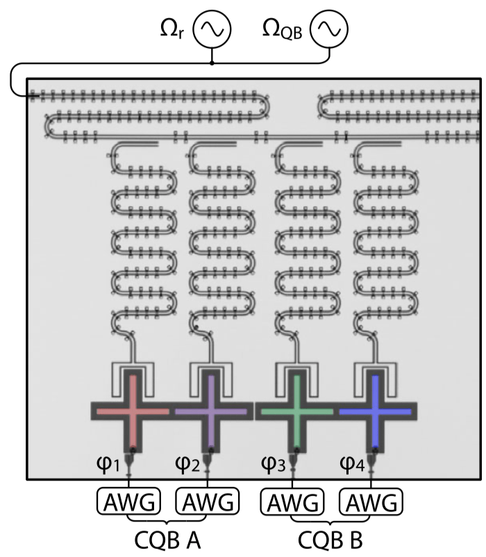
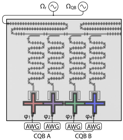
Optical image of two composite qubits, () is the reduced magnetic flux that determines the frequency of each transmon, controlled in real time by the arbitrary waveform generators (AWGs); and are the microwave control fields for qubit state readout and initialization, respectively.
The composite qubit is formed by two transmons capacitively coupled together. When using a single transmon as a qubit, its energy eigenstates are used to encode information so that and where denotes the transmon index. A single transmon qubit has frequency –that is, the energy difference between its ground state and the excited state . This frequency is controlled by the magnetic flux threading the SQUID loop of the transmon circuit. In the figure below, the dashed lines show the transmon frequency as a function of the reduced magnetic flux where is the magnetic flux quantum. As two transmons are flux-tuned to and they should have the same frequency . But instead of their energy levels crossing an energy gap called an “avoided crossing”appears for the coupled transmons (solid lines in the plot below). The magnitude of the avoided crossing is 65 MHz in this device, and it depends on the coupling strength between two transmons. (For an intuitive and pictorial explanation of avoided crossings, I recommend this wonderful article with a classical example of coupled mechanical oscillators.)
Qubit energy spectrum as a function of the flux biases; dashed lines: frequencies of bare transmon states (diabatic states); solid lines: frequencies of the coupled two-transmon states (adiabatic states). The avoided crossing of size 65 MHz appears at when two transmons are biased at the same frequency .
At the avoided crossing, the eigenstates of the system are the equal superposition states of bare transmon states which we use to define a computational basis of a qubit: . By this definition, the composite qubit has the frequency of the gap =65 MHz.
The composite qubit device emulates the following qubit Hamiltonian: , with states and associated with the eigenstates of , and the bare transmon states and associated with the eigenstates of . The parameter in the second term is determined by the frequency difference between the two bare transmons , and is controlled by varying the flux biases on the individual transmons simultaneously as a function of time. As we expect, at the composite qubit operating point , the qubit exhibits an energy splitting of .
Landau-Zener interference
To understand how gates are implemented in this new qubit, we must first understand Landau-Zener interference. For a system described by the aforementioned Hamiltonian , let’s denote its instantaneous eigenstates as and , corresponding to the lower and the higher energy eigenstates, respectively. The adiabatic theorem tells us that if the qubit state is initialized in one of the eigenstates, say , and if the time-dependent term in the Hamiltonian changes infinitely slowly, then the qubit always remains in that eigenstate throughout the evolution. However, If is varied such that the system traverses the avoided level crossing region in a finite time, a transition between two energy levels can occur and the final state becomes a linear combination of two instantaneous eigenstates. This transition between two energy levels that takes place while traversing the avoided crossing is called the Landau-Zener transition. It acts as a coherent beam splitter for a qubit state. The transition probability from state to is defined and depends on the size of the avoided crossing as well as the “velocity” of traversing the avoided crossing region . (For a pedagogical derivation of this formula, see Vutha). Moreover, if the is varied periodically such that the system traverses the avoided crossing multiple times, a sequence of LZ transitions can be induced. The phase accumulated between successive LZ transitions can constructively and destructively interfere in a controlled manner, which can be used to create a general superposition state.
In the following, we will see, the adiabatic evolution (i.e. varying slowly) is used for state initialization. The non-adiabatic LZ transitions induced by quickly varying at the avoided crossing are used to implement gates to modify quantum states.
Qubit state initialization
To use the composite qubit to encode information, one needs to be able to initialize it into the computational states or . The state initialization protocol makes use of adiabatic evolution: we vary the system ( in this case) very slowly such that if the system starts in an eigenstate of the initial Hamiltonian, it ends in the corresponding eigenstate of the final Hamiltonian. Let’s go through it step by step, and it will become clear exactly how slow the change in needs to be.
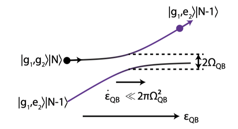
Energy levels of transmons 1 and 2 in the presence of a coherent microwave field with frequency and amplitude .
Start with both transmons in their ground states (corresponds to the filled in black circle in the figure above). This is achieved by waiting a sufficient time for the transmons reach the thermal equilibrium as the transmon temperature (around 40 mK at the bottom of the dilution fridge) is much smaller than their energy gaps (around 7 GHz for both transmons) so that and the transmon thermal state is approximately its ground state. Then turn on a static coherent microwave drive field of frequency ; this drive hybridizes the states and as shown in the diagram above, and causes a splitting with magnitude in the qubit energy spectrum. This splitting is known as the Autler-Townes splitting, and describes how the energy spectrum of an atom is modified when an oscillating electric field is close to resonance with the atom transition frequency.
Sweep the frequency of transmon 2 by tuning its flux bias . Let be the detuning between transmon 2 frequency and the drive frequency , and sweep through the drive frequency slowly such that the transmon state adiabatically evolves to (to the filled in purple circle in the figure above). The final occupation probability of state (i.e., the probability of remaining in the upper energy level during the sweep) is given by one minus the Landau-Zener transition probability . Thus we see that high-fidelity state initialization requires that the change in transmon 2 frequency be slow enough such that .
Turn off the drive, adiabatically tune the transmons in fluxes to the composite qubit operating point so that the qubit state adiabatically evolves to .
Similarly, one can prepare the logical state by adiabatically evolve the state: . It takes about 250 ns to complete the above state initialization steps; this is mostly limited by how slow the change of the system needs to be to meet the adiabatic condition .
Single-qubit gates
In the following, we will talk about some elementary gates that are used to manipulate the state of a single composite qubit, namely, the X, Y and Z gates. The X and Y gates change the probabilities of measuring the qubit in a state or , whereas the Z gate modifies the relative phase between states and . Their operations can be visualized in the Bloch sphere representation as rotations of the qubit state around the -, – and -axes, respectively. In composite qubits, the single-qubit gates are implemented through the transmon flux controls . The physical set-up involves using arbitrary waveform generators (AWGs) to generate electrical current waveforms in the transmon circuits. This in turn leads to the time-dependent magnetic fluxes to control the transmon frequency difference as desired.
-gates
The flux control pulse to implement Z gates, .
A -gate implements a rotation around -axis in the Bloch sphere representation of qubit states. This rotation is described by a unitary operator, parameterized by a rotation angle : . The Z-gate of the composite qubit is realized by simply idling the qubit (that is, biasing the qubit with a constant magnetic flux) at the avoided crossing , as shown in the schematic above, and letting the qubit evolve under the Hamiltonian for some gate time . Governed by the Schrodinger equation, the evolution of the state from the initial state to the final state after applying Z-gate is given by an unitary operator , i.e., , where – this is exactly the unitary we need to realize a -gate; the gate time controls the rotation angle .
and gates
In transmon qubits, X and Y gates are conventionally implemented by subjecting a qubit to a continuous microwave driving field on resonance with the qubit. If the qubit has non-degenerate energy levels, under this drive, the probability amplitudes of the qubit state on its ground and excited states oscillate – this oscillation is referred as the Rabi oscillation. For a transmon qubit with a frequency of a couple of gigahertz, the gate time of this type is on the order of tens of nanosecond. How fast and how accurately these gates can be implemented are restricted by the validity of the rotating wave approximation. This approximation allows one to neglect the fast-oscillating terms in treating and describing Rabi oscillations, and it only holds true for qubits with large transition frequencies. For a composite qubit with a small gap on the order of tens of MHz between between its computational states, the Rabi drive will be complicated to deal with, both mathematically and practically, due to the breakdown of this approximation. The alternative solution here, as you may have already guessed, is to use LZ transitions in small-gap qubits to manipulate qubit states.
Take the single-qubit gate as an example; in the Bloch sphere representation, this gate rotates the qubit state about the -axis by an angle . The schematic below shows the control for its implementation. This protocol is designed to induce non-adiabatic LZ transitions at the avoided crossings to manipulate the qubit’s state. Specifically, the control pulse contains a period of sinusoid pulse with idling operations (i.e., constant flux biases at the avoided crossing, equivalent to Z-gates) padded before and afterwards.
The flux control pulse to implement X gates
During the implementation of the gate, the flux controls on two coupled transmons are varied simultaneously with respect to the avoided crossing. Let denotes how much the flux controls are biased away from the avoided crossing bias point (i.e., and ), let be the instantaneous eigenstates of the time-dependent Hamiltonian so that , and let be the energy gap between two states. The plot below shows how the qubit energy gap changes with respect to the flux detuning , which is varied in time as shown in the lower panel of the plot.
Upper: the measured CQB excited state spectroscopy to form a two-level system; lower: non-adiabatic control implemented by a non resonant sinusoidal excursion about the avoided crossing.
The dashed lines in the lower panel marked at 1, 2 and 3 correspond to the start, the middle and the end of the sinusoidal flux tuning. Here is a glance of what happens to the qubit state during this sinusoidal excursion about the avoided crossing :
At () an LZ transition takes place as the qubit state leaves the avoided crossing.
During () phase accumulates between the two qubit eigenstates.
At () another LZ transition takes place when the qubit traverses the avoided crossing.
During () phase accumulates between the qubit eigenstates (the same as what happened during ).
At () another LZ transition takes place when the qubit returns to the avoided crossing.
To better illustrate this process, let’s redraw the previous plot of the qubit energy levels during the sinusoid pulse as a function of time:
A sketch of the time-dependent qubit energy levels during the sinusoidal flux pulse.
The non-adiabatic LZ transitions induced at the time points 1, 2 and 3 are described by a unitary operator . Thus, the occupation amplitude in the upper and lower eigenstates interfere, resulting in the state transitions with the probability , and a relative phase introduced between and .
During the adiabatic evolution from time 1 to 2 and from time 2 to 3, the upper energy state acquires a phase relative to the lower energy level ; no LZ transition is encountered due to adiabaticity. For the evolution , the phase accumulated is . Geometrically this can be interpreted as the area under the curve (the shaded yellow area above). Similarly, for the evolution the accumulated phase is (the shaded blue area above).
The process described above is, in effect, an interferometer made out of beam splitters placed at the avoided crossings; the fast changing fluxes near in the sinusoid induce transitions between the upper and lower energy branches just like how a beam splitter splits light into different optical paths. Similarly, the slow changing fluxes away from contribute to the phase evolution and set the stage for constructing and destructive interference between successive LZ transitions just like how sources of light creates interference pattern depending on their relative phase. The differences between the two scenarios are as follows: the optical interference is between photons, while here the interference is between quantum states of a superconducting qubit; the optical interference pattern is determined by the optical length, while here the interference happens in the phase space and is determined by the time-dependent qubit energy splitting; and lastly the qubit LZ interferometer is more fragile than an optical interferometer since photon states are very robust to decoherence.
As explained above, the evolution under the sinusoidal flux pulse can be seen as a combination of X-rotations (state transition) and Z-rotations (phase evolution). Padded Z-gates are introduced to cancel out the excess Z-rotation to implement a pure X gate with a desired rotation angle. The start of the pulse, once chosen, establishes an x-axis of the Bloch sphere. The gate, a rotation around y-axis, is then implemented by advancing the onset of the pulse by the time which corresponds the gate time of a gate, i.e., , as shown below.
The flux control pulse to implement Y gates
The frequency of the sinusoidal pulse realized by the flux controls is chosen to be = 125 MHz (corresponds to a 8 ns sine pulse). The frequency of the sine pulse (thus determines the gate time) is chosen such that the passage through the avoided crossing is fast enough to induce LZ transitions, but also not too fast so fast that successive LZ transitions overlap with each other. The flux control can be easily realized using an arbitrary waveform generator. Compared with the Rabi-type of gates where one needs to modulate the microwave signal at several gigahertz which require expensive microwave generators and IQ mixers, the type of gates here using LZ interference are simpler and cheaper to implement in the hardware.
Let’s overview how quantum computation would proceed using a composite qubit. It begins by initialization the qubit in the computational state or using the adiabatic evolution we described previously via a static microwave field. The single-qubit X and Y gates are implemented using LZ interference, and the Z gate is implemented by the idling operation. To complete a universal gate set for quantum computation, the two-qubit controlled-Z (CZ) gate is also demonstrated in the paper by turning on an effective interaction between two composite qubits. This interaction is realized by adiabatically tuning the frequency of the second composite qubit to realize an avoided crossing that evolves the second excited state of the bare transmons – this operation is similar to how a CZ gate is implemented between two standard transmon qubits. The composite qubit state is read out by uniquely mapping the computational states and to the bare transmon states and by the adiabatic evolution, and then read out through the readout resonators as in standard transom qubits.
Noise immunity
Finally, let me discuss why it is better to use two transmons instead of one as a qubit. Recall we choose the eigenstates of the coupled transmons at the avoided crossing as the qubit states and . Remarkably, this choice of computational basis allows immunity to certain noise process. For example, the processes of thermal excitation and energy relaxation (the former causes the transition and the latter ) are sources of errors in a single transmon qubit. However, to cause a transition between the qubit computational states and , it takes a correlated excitation and relaxation event to flip the states of both transmons. Flipping the states of both transmons is less likely to happen as it requires a correlated two-photon interaction with the environment; this makes the composite qubit states insensitive to uncorrelated state transitions in single transmons. As a figure of merit for qubit lifetime, the time measures the timescale on which state transition between qubit states occurs. The measured of a composite qubit is longer than 2 ms – this is 2 orders of magnitude longer than that of a single transmon. The relaxation process to the state , however, takes the qubit state out of the computation subspace – this happens on the timescale of tens of microseconds (comparable to the time of the bare transmons). The good news is that this leakage error can be detected by continuously monitoring the readout resonators when biased at the avoided crossing, since the leakage to state will result in a shift on the resonant frequency of the readout resonator; while errors of this sort can occur, they are easily detectable.
Furthermore, the composite qubit is robust to the frequency fluctuations in individual transmons; for example, in a single transmon qubit the frequency fluctuations due to environmental flux noise and the photon shot noise from the readout resonator cause the qubit to decohere. However, when biased at the avoided crossing, the qubit frequency of the composite qubit is determined by the fixed coupling strength between two transmons, and thus is insensitive to bare transmon frequency fluctuations. Another figure of merit for the qubit lifetime is the qubit decoherence time , which measures the time scale on which the qubit goes from a maximal superposition state to a classical probability mixture. The time of the composite qubit, measured in a Hahn echo decay experiment, is reported to be greater than 23 s which is much larger than the of 3 s for a single transmon qubit.
I hope now you are convinced that it is worthwhile to use two transmons as one qubit to gain protection against certain environmental noise. With the protected computation states come the new challenges in performing state initialization and state manipulate for qubits in low frequency regime. The authors of the paper demonstrate that it is feasible to use adiabatic evolution to initialize states in a qubit with frequency below the environmental temperature, and to use the Landau-Zener interference to perform fast qubit gates.
The solutions demonstrated here can be extended to other types of small-gap superconducting qubits with near-degenerate eigenstates. For instance, the gate operations using the Laudau-Zener interference has been implemented in the early pioneering works on superconducting charge qubits, more recently in fluxoniums, and may be found useful in some new qubit designs, for example, the 0- qubit, the very small logical qubit (VSLQ) design. The results of today’s paper highlight an inexpensive flux control protocol that performs universal control in small-gap superconducting qubits, paving the way to a more scalable hardware architecture as researchers push for larger qubit numbers.
Haimeng Zhang is a PhD student in Electrical Engineering at the University of Southern California. Haimeng’s research focuses on non-Markovian dynamics and quantum error suppression protocols in superconducting qubits.
 (
( ) is the reduced magnetic flux that determines the frequency of each transmon, controlled in real time by the arbitrary waveform generators (AWGs);
  and
and  are the microwave control fields for qubit state readout and initialization, respectively.


 65 MHz appears at
  when two transmons are biased at the same frequency
  .
.


 and amplitude
 (corresponds to the filled in black circle in the figure above). This is achieved by waiting a sufficient time for the transmons reach the thermal equilibrium as the transmon temperature (around 40 mK at the bottom of the dilution fridge) is much smaller than their energy gaps (around 7 GHz for both transmons) so that
and the transmon thermal state is approximately its ground state. Then turn on a static coherent microwave drive field of frequency
; this drive hybridizes the states
and
as shown in the diagram above, and causes a splitting with magnitude
in the qubit energy spectrum. This splitting is known as the Autler-Townes splitting, and describes how the energy spectrum of an atom is modified when an oscillating electric field is close to resonance with the atom transition frequency.
of transmon 2 by tuning its flux bias
. Let
be the detuning between transmon 2 frequency and the drive frequency
, and sweep
. Thus we see that high-fidelity state initialization requires that the change in transmon 2 frequency be slow enough such that
.
so that the qubit state adiabatically evolves to
.


 -gates
 .
.


![U(t_d)=\exp[-iH_z(t_d)]](https://s0.wp.com/latex.php?latex=U%28t_d%29%3D%5Cexp%5B-iH_z%28t_d%29%5D&bg=ffffff&fg=010101&s=0&c=20201002)

 and
and  gates
gates


(
(
) phase accumulates between the two qubit eigenstates.
(
(
) phase accumulates between the qubit eigenstates (the same as what happened during
(