Title: Fast logic with slow qubits: microwave-activated controlled-Z gate on low-frequency fluxoniums
Authors: Quentin Ficheux, Long B. Nguyen, Aaron Somoroff, Haonan Xiong, Konstantin N. Nesterov, Maxim G. Vavilov, and Vladimir E. Manucharyan
First Authors’ Institution: Department of Physics, Joint Quantum Institute, and Center for Nanophysics and Advanced Materials, University of Maryland
Status: Preprint: https://arxiv.org/abs/2011.02634
Introduction
We exist in the era of noisy intermediate-scale quantum (NISQ) processors [1], currently available in the form of two 53-qubit processors made by IBM and Google. These are very promising for simulating many-body quantum physics, as was recently demonstrated when Google’s Sycamore processor claimed a “quantum advantage” [2]. NISQ processors, however, are still limited in processing power due to their small size and the presence of noise in quantum gates.
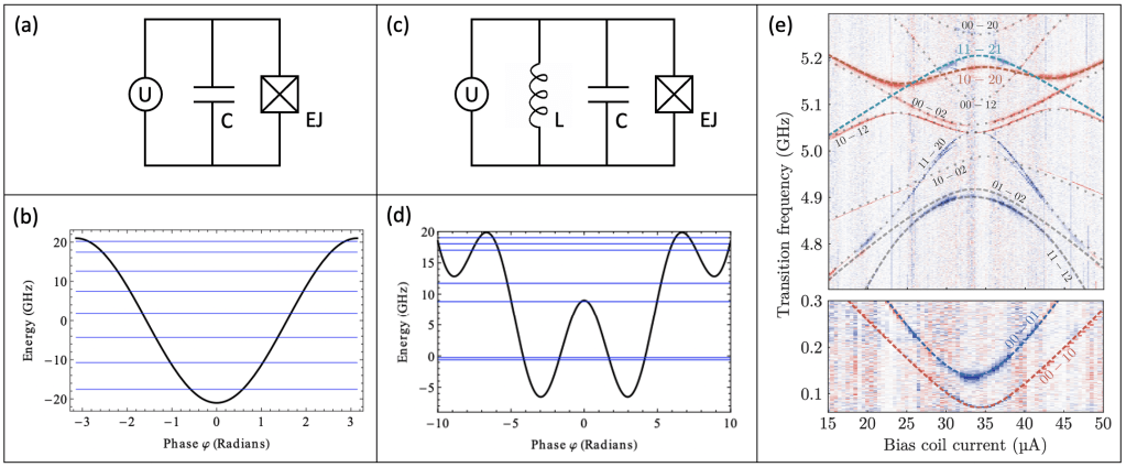
The commonality in current NISQ processors is their qubit implementation: the transmon. The transmon is composed of a capacitor in series with a Josephson junction (Fig 1a), effectively a weakly-anharmonic electromagnetic oscillator (Fig 1b). First demonstrated in 2007 [3], it has been widely adopted in many-qubit processors as it is a very simple design to implement. The transmon’s weak anharmonicity, however, is its limiting factor for current performance and further scaling.
There are many promising alternatives to the transmon, Fluxonium being a favorite because of its incredible high anharmonicity and subsequent long coherence times (with observed 

Let us first consider the simplest form of circuit-circuit coupling: mutual capacitance (Fig 2a). With two fluxonium circuits, the coupling term is proportional to 


 and
and  , which are detuned by
  . This detuning is due to repulsion between
  and
and  caused by the
  coupling.
In a previous paper [7], the authors describe how one can use these coupled subspaces to perform a microwave activated control-Z (CZ) gate between two fluxoniums by applying a 2pi-pulse between the 
When one applies a CZ gate, if qubit 2 is in the ground (0) state, this transition on qubit 1 will not occur. However, if qubit 2 is in the excited (1) state, this transition on qubit 1 will occur! You can now readout the state of qubit 2 and infer the state of qubit 1! Read more about quantum logic gates here.
The nearby transition 
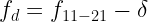
Is it possible to speed up this gate without significantly decreasing gate fidelity via leakage to the nearby
If we apply a constant drive tone 


 and , which are separated by . The Rabi drive tone
  is detuned from by
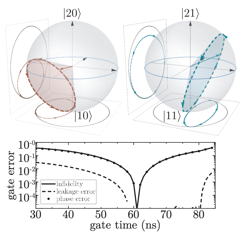
  such that full Rabi oscillations for both transitions are completed in the same amount of time. (b) Cones traced by each state vector on the Bloch sphere due to the applied Rabi drive tone, . Note the projection of these paths trace circles in opposite directions. (c) Optimal gate time of ~61 ns was chosen to minimize infidelity, leakage error, and phase error.
What is really interesting is that the detuning 


As observed from the center of the Bloch sphere, one will notice that the two oscillating state vectors travel in different directions and define two distinct cones inside the spheres (see Fig. 3b again, noting the projection of the paths). These cones define the solid angles 
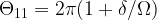

Since these two transitions are now distinguishable by their geometric phase, the authors can then apply a unitary operation U = diag(1, 1, 1, 


Basically, the 
Now that this leakage cancellation has been performed, the authors determine the shortest gate time possible with sufficient fidelity by using Optimized Randomized Benchmarking over a variety of pulse parameters. Given their specific device parameters for their two fluxoniums (see their paper for these details), this results in an optimal gate time of ~ 61 ns. This is a huge improvement over the ~ 450 ns required without any leakage cancellation! Further, the ratio of coherence time : gate time (347 
Final Remarks
Typically, a two-fluxonium system would have very long gate times. While it can have very high coherence, slow gates make it less ideal for large scale quantum processors. However, one can engineer the system using synchronized Rabi oscillations and a control-Phase operation to significantly shorten CZ gate times. By doing this, the authors demonstrated the best ratio of gate speed to coherence time that we know of to-date! Even though these fluxonium are about fifty times slower than transmons (ie. their coherence is about fifty times longer), the two-qubit gate is faster than microwave-activated gates on transmons, with gate error comparable to the lowest reported. Further work can be done by testing this procedure on other phase accumulation processes and in other two-qubit systems.
The only remaining factor preventing the development of large scale fluxonium processors is fabrication. A simple meandering inductor is physically limited by its maximum impedance. Instead, one can either use an array of hundreds of Josephson Junctions (as in this paper, Fig. 2a) or a NbTiN nanowire [8] to create this large inductive element. Current limitations in fabrication make fluxonium much more difficult to create than a transmon; however, we can expect fabrication techniques and equipment to improve in the future, making fluxonium a more viable option for scaling up NISQ processors!
References
[1] Preskill, John, “Quantum Computing in the NISQ era and beyond”, https://arxiv.org/abs/1801.00862
[2] Arute, F., Arya, K., Babbush, R. et al., “Quantum supremacy using a programmable superconducting processor”, https://www.nature.com/articles/s41586-019-1666-5
[3] Koch, J., Yu, T. M. et al, “Charge insensitive qubit design derived from the Cooper pair box”, https://arxiv.org/abs/cond-mat/0703002
[4] Masluk, Nicholas Adam, “Reducing the loss of the fluxonium artificial atom”, https://qulab.eng.yale.edu/documents/theses/Masluk,%20Nicholas%20A.%20-%20Reducing%20the%20losses%20of%20the%20fluxonium%20artificial%20atom%20(Yale,%202012).pdf
[5] Nguyen, L. B. et al., “The high-coherence fluxonium qubit”, https://arxiv.org/abs/1810.11006
[6] Zhang, H. et al., “Universal fast flux control of a coherent, low-frequency qubit”, https://arxiv.org/abs/2002.10653
[7] Nesterov, K. N., Pechenezhskiy, I. V., Wang, C., Manucharyan, V. E., and Vavilov, M. G., “Microwave-activated controlled- Z gate for fixed-frequency fluxonium qubits”, https://arxiv.org/abs/1802.03095
[8] Hazard, T. M. et al., “Nanowire superinductance fluxonium qubit”, https://arxiv.org/abs/1805.00938
