Authors: Uwe von Lüpke, Yu Yang, Marius Bild, Laurent Michaud, Matteo Fadel, and Yiwen Chu
First Author’s Primary Affiliation: Department of Physics, ETH Zurich, Zurich, Switzerland
Manuscript: Published in Nature Physics
Introduction
Superconducting qubits are a promising candidate for functional quantum computation as well as investigating fundamental physics of composite quantum systems where superconducting qubits are coupled to other quantum degrees of freedom. The most common example of this is circuit quantum electrodynamics (cQED), where a superconducting qubit is coupled to an electromagnetic resonator, and the resonator can be used to control and read out the quantum state of the qubit. In an analog to cQED, it is possible to replace this electromagnetic resonator with a mechanical resonator – this now allows for the study the quantum limits of mechanical excitations in a field commonly known as circuit quantum acoustodynamics (cQAD). By coupling a superconducting qubit to a mechanical resonator in this fashion, physicists are able to draw upon the rich and developed field of cQED to study not only further applications in quantum information science using cQAD as a building block, but also the fundamental physics of mechanical resonators in their quantum limit. In addition to the ability to study new physics, acoustic resonators are much more compact due to the slow speed of sound (relative to the speed of light which would be used in an electromagnetic cavity!) leading to much smaller wavelengths at high frequencies. In cQED/cQAD the interaction between the qubit and the resonator is often described by the Jaynes-Cummings Hamiltonian:

Here the first term in the Hamiltonian describes the resonator as a harmonic oscillator with a transition frequency 


In this recent paper published in Nature Physics, the authors demonstrate strong coupling between a superconducting qubit and an HBAR (high bulk overtone acoustic resonator)[1]. HBAR devices launch mechanical excitations (called phonons) by using the piezoelectric effect. This means that the polarization and the mechanical strain in the material are not independent – by applying an electric field to a piezoelectric material it is possible to create mechanical excitations! The device in this experiment uses a thin film of piezoelectric aluminum nitride (AlN) patterned onto a small sapphire chip. This substrate is then sandwiched together with another chip containing a superconducting qubit which acts as an anharmonic oscillator. By carefully aligning the two chips relative to each other, the authors are able to couple the electric field of the qubit to the piezoelectric material on the chip containing the HBAR and thus couple the degrees of freedom of the qubit to the phonon modes in the HBAR (see Fig. 1 for a description of the device). The joint quantum acoustics system is then loaded into an electromagnetic cavity, which will also couple to the qubit and allow for the control and measurement of the device.
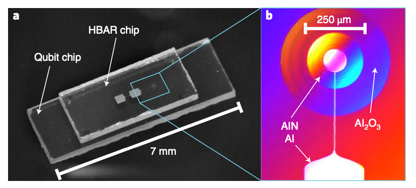
(a) View of the hybrid flip-chip device. Both large substrates are sapphire, which is transparent and thus makes it much easier to align the two chips to a high precision. The substrate that contains the superconducting qubit is on the bottom and slightly larger than the top chip which contains the HBAR resonator. (b) Optical microscopy image of the small disc of piezoelectric AlN which is responsible for the creation of phonons.
Measurement of Phonon Lifetime
By applying strong microwave signals into the system, the qubit frequency is able to be moved around by a small amount such that the qubit’s resonant frequency can be equal to the resonant frequency of the phonon mode. In this case, the qubit and mechanical system will transfer exctations to each other in the time 
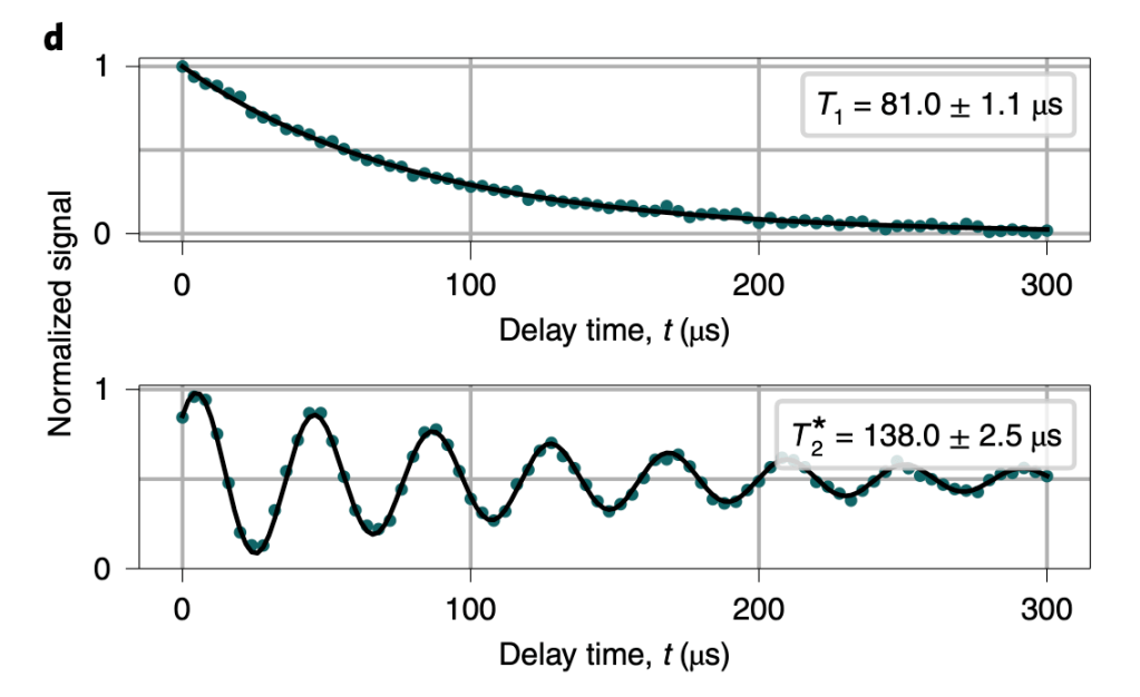
Measurement of phonon lifetime in the HBAR resonator using the experimental protocol described in the section above (top). A measurement of the phonon dephasing rate is also measured by preparing a qubit superposition state and then preforming the swap operation into the phonon resonator (bottom).
Measurement of Phonon Coherent States
By applying a strong tone to the system which is resonant with the HBAR device, the HBAR device will be placed into a coherent state which can be written down as a sum of Fock states:
In order to determine how this will impact the spectral features of the qubit, it can be helpful to look at the probability of having $m$ phonons given a certain coherent state 


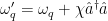
The Hamiltonian which describes the interaction between the qubit and mechanical modes in the regime where the detuning (

Where here the dispersive shift 


By changing the amplitude of the signal, the authors are able to vary the mean phonon number injected. This is measured by observing the qubit spectra split into multiple peaks each representing different phonon numbers, with each peak. Then, by comparing the relative height of each peak, the authors are able to determine the corresponding phononic coherent state. See Fig. 3 for the resulting measurement. Additionally, the authors see that there is a linear relationship between the mean phonon number and the strength of the signal generating the phononic coherent state, as expected.
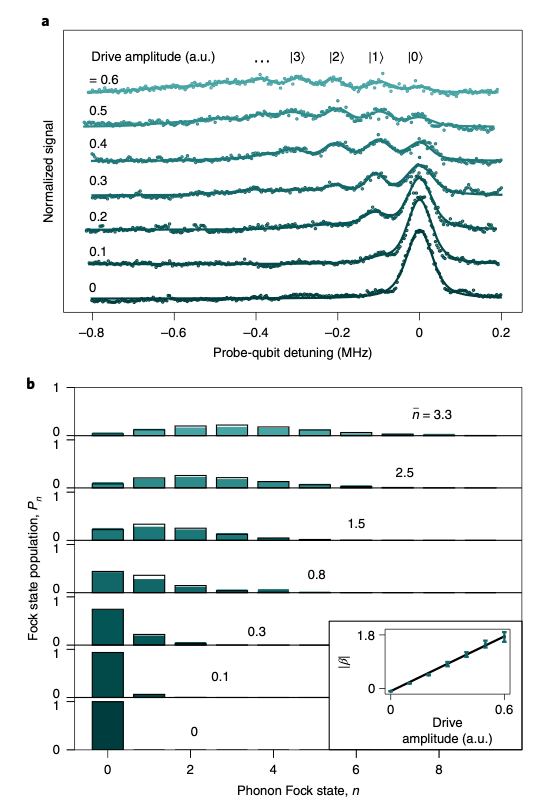
(a) Measurement of the qubit absorption spectrum as a function of drive amplitude for the signal displacing the HBAR’s coherent state. At low drive amplitudes, the qubit spectra has a single peak, while at high drive powers, the qubit spectra splits into many peaks, each one indicating a different phononic Fock state. (b) Extraction of the probability of each Fock state at different drive amplitudes. The extracted probability distribution in Poissonian in the phonon number, as would be expected for a coherent state. The authors also find that the mean phonon number in the HBAR is linear in drive amplitude (inset).
Parity Measurement of Phonon Number
After investigating the qubit’s response to phonon states in the frequency domain, the authors look to the qubit response in time to learn about how the presence of phonons impacts the qubit. By repeatedly preparing the qubit into its excited state and preforming multiple swap operations between the qubit and the HBAR device, it is possible to prepare higher number Fock states (by quickly adding many excitations into the HBAR device one at a time). This is done by first exciting the qubit, swapping the excitation into the mechanical resonator, and repeating to add more excitations to the HBAR. After preparing the mechanical resonator’s state, the authors put the qubit into a superposition state: 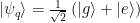


(a) Measurement of qubit absorption spectra when the HBAR is prepared in different Fock states. Rather than seeing the spectra split into several different peaks here (as in Fig. 3a), the authors find that the qubit spectra remains largely constant, only the center frequency of the qubit is shifted proportional to the number of phonons in the HBAR resonator. (b) Ramsey measurements of the qubit. Here, the frequency of oscillation of the Ramsey decay allows the authors to extract the phonon number in the HBAR resonator. Importantly, at
 , the authors are able to determine the parity (even-ness or odd-ness) of the phonon number in the HBAR resonator. (c) Comparison of measured parity based on two measurement schemes described by spectroscopic measurements (panel (a)), as well as measured parity by Ramsey measurements (panel (b)), the authors find very good agreement in measured parity between the two measurement schemes!
Conclusion
In this experiment, the authors demonstrate a hybrid quantum acoustics experiment which operates in the strong dispersive regime, where the dispersive interaction between a superconducting qubit is much stronger than either the loss of the qubit or the loss of the HBAR resonator. By entering this special regime of circuit quantum acoustodynamics (cQAD), the authors are able to perform experiments which allow them to probe the quantum properties of high frequency sound. By using special experimental techniques, the authors are able to create non-classical phonon states in the HBAR resonator (Fock states) and determine phonon parity based on two separate measurement schemes.
References:
[1] U. von Lupke, Y. Yang, M. Bild, L. Michaud, M. Fadel, and Y. Chu, Parity measurement in the strong dispersive regime of circuit quantum acoustodynamics, Nature Physics 10.1038/s41567-022-01591-2 (2022)
Many thanks to Akash Dixit for his many helpful comments and suggestions in the writing of this summary!
