This post was sponsored by Tabor Electronics. To keep up to date with Tabor products and applications, join their community on LinkedIn and sign up for their newsletter.
Authors: P.M. Harrington, M. Naghiloo, D. Tan, K.W. Murch
First Author’s Primary Affiliation: Department of Physics, Washington University, Saint Louis, Missouri 63130, USA
Manuscript: Published in Physical Review A
Introduction
Quantum systems are generally very sensitive, and upon interacting with the environment, their quantum properties can decohere. This essentially makes a given quantum system dissipate into purely classical behavior. However, in certain contexts it is possible to use dissipation in a controlled fashion to increase the control of quantum systems. A few examples of controlled dissipation in this way include laser cooling of atoms, cooling of low frequency mechanical oscillators, and for the control of quantum circuits. In this recent publication [1], the authors are able to demonstrate stabilization of superposition states in a superconducting qubit using a custom made photonic crystal loss channel. By considering how the photonic crystal induces loss on the system, the authors provide a master equation treatment which explains how the combination of a specialized drive applied to the qubit in addition to the dissipation provided via the photonic crystal allows for precise control of the qubit state for times much longer than standard qubit coherence times.
Experimental Details
This experiment consists of a superconducting qubit whose dipole moment is coupled to the electric field inside of a three dimensional waveguide cavity. In this experiment, the role of the waveguide cavity is to provide microwave control of the qubit as well as reading out the state of the qubit. The superconducting qubit consists of two Josephson junctions in parallel, forming a superconducting quantum interference device (often referred to as a “SQUID”). This allows the authors to change the resonant frequency of the qubit by threading an external magnetic field through the SQUID loop. On the output of the waveguide cavity, the authors connect a photonic crystal to the circuit. This photonic crystal is made out of a regular coaxial cable which is mechanically deformed in a specific way in order to change the impedance of the cable. The result of the spatially varying impedance in the cable leads to the opening of a bandgap – leading to photon energies (or frequencies) where the photonic density of states is zero (see Fig. 1 for a schematic of the experimental setup). By changing the photonic density of states as a fucntion of energy, the decay of the qubit will also change as a function of frequency.
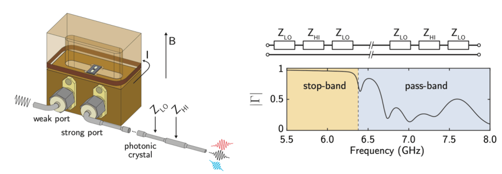
Left: Schematic of the experimental system. The superconducting qubit is mounted in a copper cavity which is used for control and readout of the qubit state. By passing current though a superconducting wire wrapped around the cavity a magnetic field is generated perpendicular to the substrate containing the qubit, allowing the authors to tune the resonant frequency of the qubit. The photonic crystal is connected to the output port of the cavity, changing the density of states that the qubit can decay into. Right: Room temperature measurements of the reflection off of the photonic crystal. In the stop-band (from 5.5 – 6.4 GHz) most of the signal sent into the photonic crystal is reflected, verifying that there is a low density of states at those frequencies. Above 6.4 GHz, the photonic band gap closes and photons can transmit through the photonic crystal.
Qubit Decay Rates
In order to measure the decay rate of the qubit, the authors first excite the qubit into its excited state by applying a pulse of energy which is resonant with the qubit to the system. They then measure the probability of the qubit remaining in its excited state as a function of time after the pulse is applied. By fitting the measured probability to an exponential decay and extracting the decay constant, one is able to determine the qubit decay rate. The resonant frequency of the qubit is then adjusted by changing the external magnetic flux threading the SQUID loop, and measuring the qubit decay rate as a function of qubit frequency in order to investigate the impact of the photonic crystal on the qubit lifetime. The total decay rate of the qubit can be written as
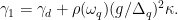
In Eq. 1, 


Measurement of qubit decay rates over a broad range in frequencies. Because the qubit loss varies quickly with qubit frequency, by flux biasing the qubit to a point where the derivative of the qubit loss is large, it is possible for Mollow triplet sidebands to sample frequencies with both very high and very low loss. By measuring the generalized Rabi frequencies across the same values of qubit frequency, the authors verify the variable couple of the qubit to the photonic crystal.
Dynamics and Emission of a Driven Qubit
After verifying that the density of states in the photonic crystal can shape the decay rate of the qubit, the authors now consider more carefully how the qubit actually emits energy. Specifically, a strong drive applied with amplitude 


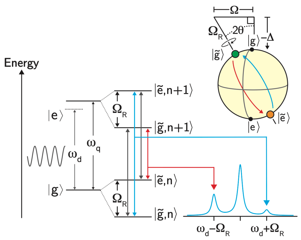
Schematic which represents the emssion of the driven two level system. Under the presence of a strong drive, the qubit emits radiation at frequencies corresponding to the drive frequency
as well as at the frequencies  . Due to the shaped loss spectrum, the area of one sideband can be supressed, indicating that the qubit will emit radiation at this frequency at a lower rate compared to the other sideband. Top right: under the presence of the drive, the quantization axis of the qubit also rotates, which changes which qubit states can be prepared/stabilized.
Because the authors have observed that the photonic crystal shapes the loss rate of the qubit on a energy scale comparable to values of experimentally accessible 
The next thing to consider is what the presence of an applied drive does to the energy spectrum of the qubit. In a frame rotating with the drive frequency, the qubit Hamiltonian is given by

where 


where the rotated Pauli Z matrix can be written as 


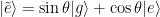
At this point it’s probably useful to consider a useful example! In the case of a resonant drive, 


Lindblad Master Equation
In the presence of the combined drive and dissipation experienced by the qubit, the dynamics of the reduced density matrix which describes the qubit can be written according to the Lindblad Master equation [3]:
![\dot{\rho} = i[\rho,H] + \gamma_0 \cos{(\theta)}\sin{(\theta)}\mathcal{D}[\tilde{\sigma}_z]\rho + \gamma_{-} \sin{^4\left(\theta\right)} \mathcal{D}[\tilde{\sigma}_{+}\rho + \gamma_{+}\cos{^4\left(\theta\right)} \mathcal{D}[\tilde{\sigma}_{-}]\rho.](https://s0.wp.com/latex.php?latex=%5Cdot%7B%5Crho%7D+%3D+i%5B%5Crho%2CH%5D+%2B+%5Cgamma_0+%5Ccos%7B%28%5Ctheta%29%7D%5Csin%7B%28%5Ctheta%29%7D%5Cmathcal%7BD%7D%5B%5Ctilde%7B%5Csigma%7D_z%5D%5Crho+%2B+%5Cgamma_%7B-%7D+%5Csin%7B%5E4%5Cleft%28%5Ctheta%5Cright%29%7D+%5Cmathcal%7BD%7D%5B%5Ctilde%7B%5Csigma%7D_%7B%2B%7D%5Crho+%2B+%5Cgamma_%7B%2B%7D%5Ccos%7B%5E4%5Cleft%28%5Ctheta%5Cright%29%7D+%5Cmathcal%7BD%7D%5B%5Ctilde%7B%5Csigma%7D_%7B-%7D%5D%5Crho.&bg=ffffff&fg=010101&s=0&c=20201002)
Here, 
![\mathcal{D}[A]\rho = \left( 2 A \rho A^{\dagger} - A^{\dagger}A\rho - \rho A^{\dagger}A\right)/2](https://s0.wp.com/latex.php?latex=%5Cmathcal%7BD%7D%5BA%5D%5Crho+%3D+%5Cleft%28+2+A+%5Crho+A%5E%7B%5Cdagger%7D+-+A%5E%7B%5Cdagger%7DA%5Crho+-+%5Crho+A%5E%7B%5Cdagger%7DA%5Cright%29%2F2&bg=ffffff&fg=010101&s=0&c=20201002)


Experimental Results
In order to verify that the authors can use the combination of drive and dissipation to prepare and stabilize qubit states, they implement the following bath engineering protocol. First, the qubit is flux biased to a resonant frequency of 6.4766 GHz (as in our example). Then, a coherent drive is applied to the system for nearly 

(a) Measurement of
as the parameters of the drive change. For certain drive parameters the value of is negative. As the drive parameters are changed, the system crosses through a region of “zero coherence” where the bath engineering protocol no longer works before stabilizing to positive values. (b) Numeric solutions to the master equation under the same drive parameters as (a). The authors observe excellent agreement between the experiments and the numeric solutions. (c) Comparison of horizontal linecuts from (a,b). The authors observe agreement between the measured values (dots) and simulated values (lines) when considering all expectation values for the qubit state ( )
)Conclusion
In conclusion, the authors are able to demonstrate the fabrication of a spatially changing impedance coaxial cable which acts as a photonic crystal, and in turn controlling the loss spectrum of a superconducting qubit. The authors are then able to leverage this shaped emission spectrum in the context of the master equation to prepare and stabilize non-trivial states of the qubit for times much longer than the coherence times of the qubit.
References
[1] P. M. Harrington, M. Naghiloo, D. Tan, and K. W. Murch, Bath engineering of a fluorescing artificial atom with a photonic crystal, Phys. Rev. A 99, 052126 (2019)
[2] B. R. Mollow, Power spectrum of light scattered by two-level systems, Phys. Rev. 188, 1969 (1969)
[3] G. Lindblad, On the generators of quantum dynamical semigroups, Communications in Mathematical Physics 48, 119 (1976).
